
The Foxboro I/A Series® represents a comprehensive and robust industrial automation platform designed for critical process control applications. The installation manual (B0193AC, Revision T, dated June 28, 2002) provides meticulous, step-by-step guidance for setting up this complex system. This article summarizes the key components and procedures outlined in the manual, highlighting the system’s structured approach to installation, from initial unpacking to final power-up.
1. System Philosophy and Structure
The I/A Series is a modular system built around various enclosures and mounting structures. This design allows for flexible configurations tailored to different environmental conditions and application needs, from standard control rooms to harsh field locations. The installation process is logically divided into distinct phases, ensuring safety, correctness, and reliability.
2. Key Hardware Components
The manual details a wide array of hardware, which can be categorized as follows:
- Enclosures: These provide the physical housing and environmental protection. Types include:
- Industrial Enclosures (IE16, IE32): For general plant floor use, available in vented or sealed types.
- Field Enclosures (FE4, FE8): Compact, sealed units designed for mounting near process equipment (pipe, wall, or floor).
- Metal Enclosures (IEMFA, IEMFR): For heavy-duty applications, offering front or front/rear access.
- NEMA 4/4X Hardened Enclosures: Rugged, waterproof housings with integrated vortex or air conditioning cooling for extreme environments.
- Mounting Structures: The internal frames that hold system electronics.
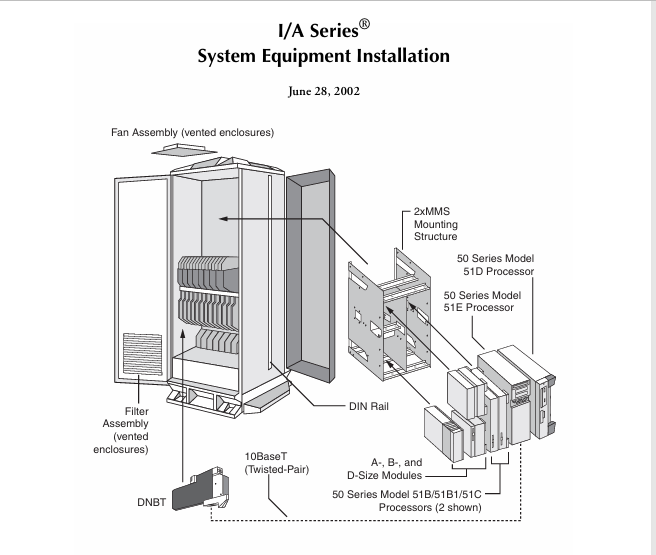
- Modular Mounting Structures (MMS, 2xMMS): For housing 50 Series processors and modules (A, B, C, D, E, F-size).
- FBM Mounting Structures (1×8, 1×12, 2×8): Dedicated structures for Fieldbus Modules (FBMs), which interface with field instruments.
- Processors & Modules: The core computing and I/O elements.
- 50 Series Processors (AP/WP/AW50/51): Application, Workstation, and Application Workstation processors in various sizes.
- 70 Series Processors: Higher-performance workstations based on PC architecture (e.g., Pentium II/III).
- Server 70 Processors: For server-level applications.
- Fieldbus Modules (FBMs): A extensive range of I/O cards (e.g., FBM01 for analog, FBM07 for digital) for connecting to field sensors and actuators.
- Legacy Modules: X-Modules and Z-Modules (e.g., Application Processor 20, various gateways and communication processors).
3. Installation Workflow
The manual prescribes a systematic installation sequence:
- Preinstallation & Unpacking: Emphasis is placed on careful handling, inspection for shipping damage, and static discharge precautions, especially for hard disk drives.
- Equipment Mounting: Detailed procedures are provided for physically securing each type of enclosure (floor, wall, pipe) and its internal mounting structures. Critical warnings highlight the mandatory separation of high-voltage power and low-voltage signal cables.
- Power and Grounding: A dedicated section covers connecting primary and secondary (redundant) AC/DC power sources to junction boxes within each enclosure. It strongly emphasizes safety (locking out power) and proper earth (ground) connections for safety and noise immunity. It also covers external battery backup and status tap installations for critical power monitoring.
- Module/Processor Installation: Instructions guide the installer on populating the mounting structures with the correct mix of modules and processors, using specific spacer kits and hardware. Procedures differ for MMS, 2xMMS, and NEMA 4/4X enclosures.
- Cabling: This extensive part of the manual covers:
- Data Storage Device Cabling: SCSI address settings and cabling for hard drives, tape drives, and CD-ROMs.
- Fieldbus & Nodebus Cabling: The backbone communications for extending control to remote I/O clusters and processors.
- Termination Cable Assembly (TCA) Installation: Connecting field wiring to the FBM termination blocks.
- Field Connections: Detailed wiring diagrams for every FBM type, specifying connections for analog (4-20mA, RTD, T/C) and digital signals.
- Peripheral & Communication Cabling: Connecting operator workstations, printers, terminals, monitors, keyboards, and third-party device gateways (e.g., Modicon, Allen-Bradley).
- Initial Power-Up: A checklist procedure to verify all connections before applying power and performing initial system checks.
4. Safety and Compliance
The manual begins with critical Hazardous Location Precautions (CSA Requirements) for Class I, Division 2 areas, warning against component substitution or disconnection without proper power isolation. This underscores the system’s suitability for use in potentially explosive atmospheres.
5. Documentation and Support
The manual references a comprehensive suite of supporting documents (e.g., Site Planning B0193AB, Hardware Descriptions B0193AE), available on CD-ROM or from Foxboro support, which provide essential complementary information for planning and configuration.
Conclusion
The Foxboro I/A Series installation manual is a testament to the system’s engineering depth and flexibility. It provides a rigorous, safety-focused framework for installing a distributed control system capable of meeting the demands of diverse and challenging industrial environments. The structured approach—from physical mounting and power hookup to intricate signal cabling and communication networking—ensures that a properly installed I/A Series system forms a reliable foundation for process automation and control.